Instructions for the shearing process of grain-oriented silicon steel
- The impact of the shearing quality on magnetic
properties of grain-oriented silicon steel - Factors affecting
the shearing quality - Regular Slitting
Process & Precautions - Common slitting
defects & solutions
The strip steel shearing process is composed of processes such as elastic deformation, plastic deformation, crack propagation and material breaking of strip steel. During the phase of elastic deformation, the upper and lower blades squeeze the strip steel, causing elastic flattening and slight bending of the strip steel. Then, as the upper and lower blades squeeze harder, the strip steel will reach its yield limit and plastic deformation will take place within the metal, in which case a neat shearing surface will be obtained. With the ongoing shearing, stress concentration happens at the cutting edge, causing tiny cracks. With the rapid expansion and overlapping of the upper and lower cracks, the strip steel break and the shearing process is completed.
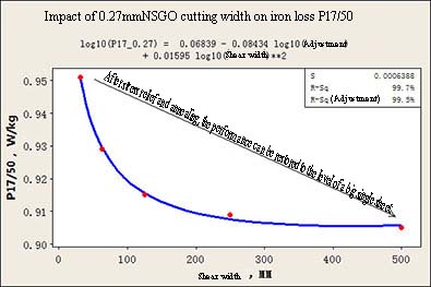
During the slitting and crosscutting process of the grain-oriented silicon steel, there will be remaining steel on shearing areas, which can cause deterioration of the electromagnetic properties of silicon steel sheets. Under the same cutting conditions, the smaller (narrower) a sheared sheet is, the more obviously the shear stress deteriorates the electromagnetic properties of the product.
Besides, apart from the shear stress, the shear quality also impacts the material in another way. That is, when the actual lamination factor of the strip steel gets smaller, the shear quality will get worse and the burrs will become bigger, causing reduction of the effective cross-section area of the iron core and increase of the actual working magnetic flux density, in which case the transformer loss will increase.
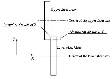
Parameters affecting the strip steel shearing quality mainly include the interval amount and the overlap amount. In normal circumstances, slitters, when used, may experience problems as follows:
1. The side interval (interval amount) is not reasonably set: If the side interval is set at a too big value, problems such as tears or rugged edges may occur during the shearing process; if the side interval is set at a too small value, it may accelerate wear of the blades and cause burrs or fins;
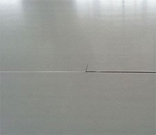
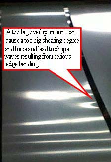
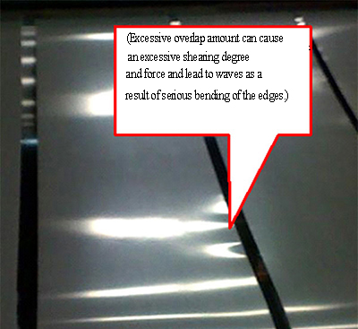
2. The overlap amount is not reasonably set: If the overlap amount is too small, the strip steel wonˇŻt be cut through during the shearing process. If the overlap amount is too big, shape waves may appear at the edges of the strip steel.
3. Some production facilities use dual-purpose tool holders, in which case the equipment may not be able to run stably when the rotating platform of the slitter is not locked tight, which can directly affect the shearing precision.
Factors affecting shearing quality >>Impact of side interval
1. According to empirical evidence, compared with the overlap amount, the side interval has a bigger impact on the edge quality. The side interval is mainly intended to reduce defects such as burrs and fins and minimize possibilities of mechanical overload. Its value is determined by the physical properties and thickness of the strip steel.
2. As for sheet cutting, the side interval is normally 1% to 10% of the thickness of the strip steel. When the material to be cut is soft and thick, a smaller side interval value out of the range should be taken; when the material is hard and thick, then a bigger side interval value should be chosen.
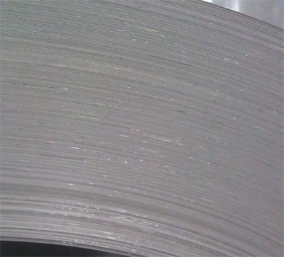
The shearing section of the strip steel can be divided into sunken shoulder a (or sunk angle), section b (or euphotic zone), tear fault c (fault zone), and burr d.
When the adjustment starts, the proportion of the section will be reduced with the increase of the side interval, and there will be basically no change to the burrs; when the side interval is increased to a certain degree, there wonˇŻt be any further obvious reduction of the section but there will be a considerable increase in burrs.
When the side interval is adjusted to too small, the tool blades will wear severely (tool wear) and the machine overload will occur. If the proportion of a section is too big, part of the section will experience secondary cutoff;
When the side interval is too big, cracks will not overlap, and the central part will be forced broken, causing an uneven section and serious burrs.

Factors affecting shearing quality >>Impact of overlap amount
The overlap amount of the shear blades should be adjusted in accordance with the thickness of the strip steel and how the shearing process is performed. Normally speaking, a too big overlap amount can cause a too big shearing degree and force and lead to shape waves resulting from serious edge bending. If the overlap amount is too small, the strip steel may not be cut through or slitter edges may come out from the chute.
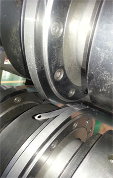
Factor affecting shearing quality >>Impact of the machining error of the shear blade
Apart from the interval amount and the overlap amount that affect the shearing quality, the machining error of the shear blade also impacts the shearing surface, repaired shears in particular. Pay attention to make sure that the perpendicularity of the working surface of the shear blade to the centerline of the mounting hole is in conformity with the requirements of the machining process.
Factor affecting shearing quality >>Impact of the raw material difference
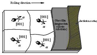
There is an insulating film and a glass film on the surface of the grain-oriented silicon steel, with the thickness of double films at around 6 to 8¦Ěm. Even for products with the same nominal thickness, the actual thickness varies with different manufacturers. For example, domestic manufacturers normally adopt the negative tolerance rolling for grain-oriented silicon steel, so the thickness tends to be smaller than that of the products of Japanese manufacturers. Even for products of the same nominal thickness that are produced by different domestic manufacturers, there can be a difference of around 5¦Ěm in terms of the actual thickness.
The shearing quality has a direct impact on the electromagnetic properties of the grain-oriented silicon steel, and the extent of impact exceeds a grade. Therefore, during the shearing process, one should, in accordance with the actual thickness of the materials provided by different manufacturers, the mechanical properties and even the difference in product coating properties, verify the pre-shearing quality before batch shearing to minimize deterioration caused by shearing to magnetism.
Factor affecting shearing quality >>Adjustment of the side interval and the overlap amount
The overlap amount and interval of tools are important factors affecting the shearing quality. During adjustment, the overlap amount should normally be adjusted first before adjustment of the interval. Beware of preventing chips resulting from collision between tools during adjustment of the overlap amount when the interval is too small.
Zero mark: Mount one of the tools in the reversed way so that two cutters can overlap vertically. Then, adjust the overlap amount to the point where the two tools completely fit each other, and mark it as the zero position;
Adjustment of the overlap amount: On the basis of the zero position, adjust the overlap amount. During the adjustment, the side interval of the tools should be appropriately increased to prevent chips resulting from collision between tools.
Adjustment of the interval: During the adjustment of the interval, one should stand at the central point between two tools and insert the feeler gauge, which should be parallel to the tools, into the interval. During the measurement with the feeler gauge, one should ensure the consistency of values of more than four points measured on the same circular surface.
Considering the issues regarding the same plate difference of grain-oriented steel, the interval between the tools in the middle is normally slightly bigger than that between the tools on the sides.


Reference values for the interval and overlap amount
| 0.3mm | Interval 0.3*Ł¨6%-10%Ł©mm |
0.018mm |
| Overlap amount 0.3*Ł¨70%-80%Ł©mm |
-0.24mm | |
| 0.27mm | Interval 0.27*Ł¨6%-10%Ł©mm |
0.015mm |
| Overlap amount 0.27*Ł¨70%-80%Ł©mm |
-0.17mm | |
| 0.23mm | Interval 0.23*Ł¨6%-10%Ł©mm |
0.012mm |
| Overlap amount 0.23*Ł¨70%-80%Ł©mm |
-0.13mm |
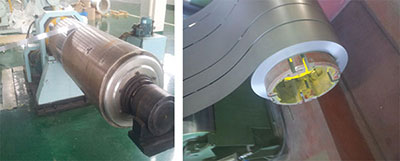
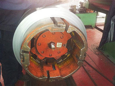
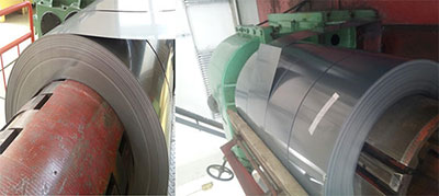
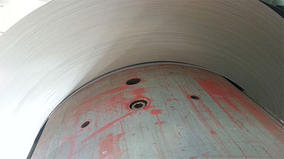
Area of the uncoiler
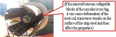
As the uncoiler doesnˇŻt have the function of automatic centering, check whether the positioning device of the uncoiler is in good condition before mounting the coil. Check whether any of the screws on the fan-shaped area of the uncoiler is loose so as to prevent impressions on the inner ring of the steel coil.
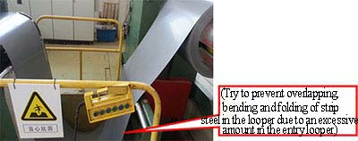
Area of the entry looper
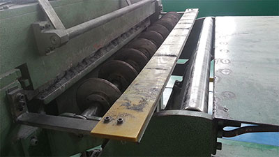
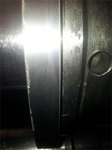
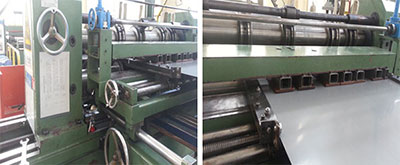
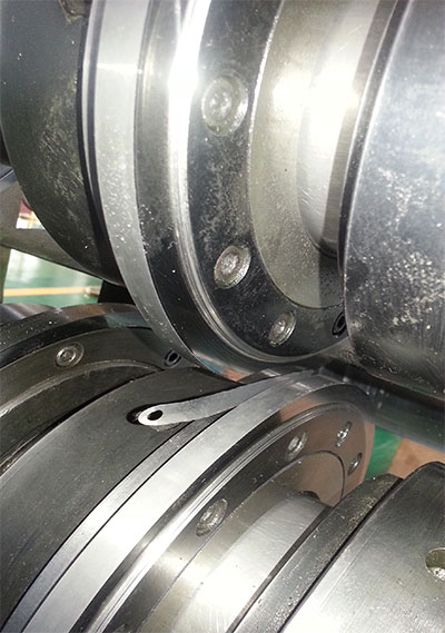
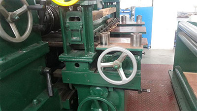
Area of shear blades
When the strip steel is put in, check the surface of the lower pinch roll at the entry for any impurities. Check the position of the front and back guide plates of the entry shears to prevent scratches on the lower surface of the strip steel due to inappropriate position of the guide plates.
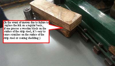
Check the upper and lower pressing plates and felt at the entry of the slitting shear for any wear. In the event of serious wear, immediate replacement must be done, and itˇŻs recommended to establish a regular replacement system.
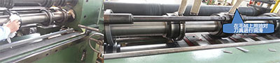
During specification change, use a clean cloth to clean the cutter shafts and shear blades at the shear blade area to prevent any negative impact on the coiling quality as a result of powders left on the surface of the strip steel.
To ensure maintenance of the shear blades, use volatile lubricant or kerosene to protect shear blades during production.
Area of the exit looper
Check the operation of the slitter within the exit looper. Prevent defects such as folds or scratches of the strip steel in the looper because the looper is too big.
If the interval of the exit looper is too small and the bending curvature of the strip steel is too big, it might have a negative impact on magnetic properties.
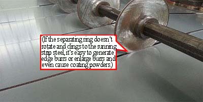
Area of the exit turning roll
Check the exit turning roll and the entry separating ring to see if the separating ring is in synchronization with the running strip steel and if there is any edge burr or coating powder on the surface.
Upper and lower pressing plates (felt) of the separating ring: Check the surface for wear on a regular basis to ensure regular replacement. Pay attention to height adjustment of upper and lower pressing plates to prevent folds of the strip steel resulting from superposition during running of the strip steel.
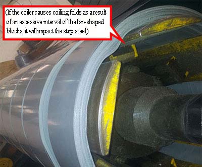
Area of the coiler
Check the fan-shaped block of the coiler for expansion and shrinkage and check the surface for impurities to prevent impressions in the inner ring.
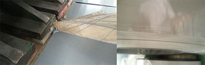
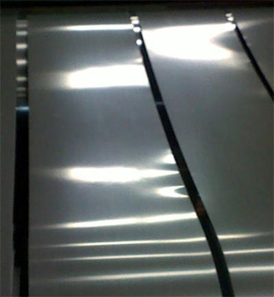
During the shearing process of the grain-oriented silicon steel, itˇŻs easy to cause defects such as shiny end faces, edge traces, edge waves and burrs. Therefore, to ensure the trimming quality, the state of the shear blades, the shear blade parameter setting, and proper adjustment are the key.
Common slitting defect >>burrs
Improper adjustment of the interval between upper and lower shear blades, prolonged use of shear blades for shearing, or small chips on shear blades can easily cause excessive burrs.
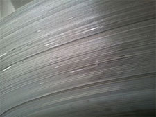
Common slitting defect >>Edge waves
Excessive overlap amount, improper adjustment of upper and lower pressing plates between shear blades, or deep pressing of the upper pressing plate can easily cause edge waves.
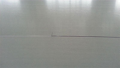
Common slitting defect >>Edge fins
If the use of shear blades is prolonged, or the interval is too big, or the overlap amount is too small, it can cause tear of end faces of the strip steel and edge fins.
Common slitting defect >>bright traces
If the shear blades have small chips, or the shear blades have been used for a prolonged period, or the interval is too small, it can easily cause bright traces on the end faces.
Common slitting defect >>Coating powder dropping
If the coating of the incoming material is too thick or the pressing plates of the slitter is too tight, it can easily cause coating powder dropping or white edges.
Solution for eliminating defects >>Preparations
The first step of the preparations that field operators are required to make before production is to check the shear blades, clean the inline shear blades, and check the end face of each shear blade of the inline shearing machine for any chip.
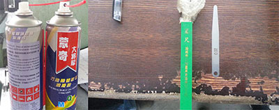
Prepare a 0.02mm feeler gauge and a 0.015mm sheet copper. Prepare the cleaning agent and volatile lubricant such as kerosene.
Solution for eliminating defect >>Cutter testing
Use the inline cutting blade to cut a piece of waste paper, and if the paper can be easily cut, itˇŻs good. Or cut a small grain-oriented silicon steel sheet, and if the cut surface is smooth and neat, itˇŻs good. Or an adjustment must be made or the shear blade must be replaced.

Solution for eliminating defect >>Reference values for the interval and the overlap amount
The interval or the overlap amount cannot be too big or too small. If the interval or the overlap amount is too big or too small, it will accelerate wear and damage of the cutting edge of the shear blade and directly impact the shearing quality of the grain-oriented silicon steel. Normally, the interval should be between 0.015 and 0.025, and the overlap amount should be between -0.10 and 0.30mm. (As for the setting of the overlap amount, if you rotate the upper cutter shaft and it can steadily and easily drive the lower cutter shaft, then itˇŻs appropriate).
Solution for eliminating defect >>Measurement of the interval
Vertically insert the 0.02mm feeler gauge into the interval between the upper and lower shearing blades along the direction of the operation to determine the interval between shear blades. If the feeler gauge goes through the interval with difficulty, then itˇŻs good. To ensure that all the intervals between shear blades on the same axis can be as consistent as possible, do not only measure a single point. Instead, mark the point of measurement, and then rotate the cutter shaft to measure points of 45ˇă, 90ˇă and 135ˇă to determine whether the interval values at different shearing points are consistent.
Solution for eliminating defect >>Measurement of the overlap amount
After the upper and lower shear blades have been slightly separated, move the feeler gauge from side to side along the axial direction of the shear shaft and insert it into the interval between the upper and lower shear blades. If it cannot go through the interval, it means that the overlap amount is less than 1mm, and the overlap should be enlarged. If it can, then the overlap should be reduced. If the intervalˇŻs just enough for a 1mm feeler gauge to go though, then the interval between the upper and lower shear blades is 1mm. On such basis, use the scale of the overlap amount on the tool holders to make the zero position marking. During production of materials with different thicknesses, the overlap amount is required to be adjusted on a timely basis.
Solution for eliminating defect >>Eliminating burrs
After shearing, take samples to check the trimming quality. If there are traces or bright traces on the cut surface of the sample sheet, or if there are some serious defects that feel like thorns. Solution: Appropriately adjust the interval to make it smaller. If the whole cut surface is white and slight grey, then it indicates that the interval is proper.
If there are periodical changes on the whole cut surface, then it indicates that the shear blade itself is buckled, or end face of the shear blade has small chips, or the jump tolerance of the shear blade after the whole assembly of the equipment is serious. Solution: The shear blade should be remounted or replaced.
Solution for eliminating defect >>Eliminating waves
The overlap amount should be 70% to 80% of the thickness of the strip steel to be cut. Take a value and make proper adjustments. The overlap amount cannot make a deep press, or waves will be caused. Solution: Adjust the overlap amount according to the thickness, and adjust the upper and lower pressing plates between the shear blades to maintain stability of the pressing plates and prevent waves resulting from a deep press from the upper pressing plate.
Solution for eliminating defect >>Eliminating edge fins
If there are edge fins on the cut surface, it indicates that the interval is too big. Solution: Properly narrow the interval or increase the overlap amount according to how serious the edge fins are.

Solution for eliminating defect >>Eliminating bright traces
If there are bright traces of scrap iron dotted on the cut surface and it feels rough, or in a more serious case, there are iron chips falling down, it indicates that the interval is too small. If the whole cut surface is smooth or shiny, it indicates that the interval is too small. If the whole cut surface is in lead gray, it means that the interval is slightly small. Solution: Enlarge the interval appropriately.

Solution for eliminating defect >>Eliminating coating powder dropping
The major cause is that the separating ring at the exit seems to be rotating while it isnˇŻt rotating. As a result, when the strip steel is running, thereˇŻs friction between the edges of the strip steel and the separating ring, causing powder dropping of the edges. Solution: During the running of the strip steel, ensure that the rotation speed of the separating ring of the inline equipment matches with the running speed of the strip steel.